IBM High-Speed 100/16/4 Token-Ring PCI Management Adapter User's Guide
This chapter describes how to install the IBM High-Speed 100/16/4
Token-Ring PCI Management Adapter.
Your adapter comes configured from the factory with RPL/PXE and
expansion ROM enabled.
Before you begin to install this adapter, be sure to read Safety Information.
To install your adapter, perform the following procedure:
- Switch OFF the PC and all attached devices.
| Note: | In the U.K., by law, telephone line cables must be disconnected
from the PC before the power cord.
|
- Remove the power cord from the outlet.
- Remove all cables from your PC. Label each cable for easier
reconnection at the end of this procedure.
- Follow the instructions provided in your PC manual for removing the cover
or otherwise accessing the adapter slots and inserting the adapter.
- Install the adapter according to the instructions for adapter installation
in the manual that came with your PC.
| Note: | If you will be using the Wake on LAN feature, then depending on the
orientation of the adapter to your computer, you might need to connect the
Wake on LAN cable to your adapter before inserting the adapter into the slot
in your computer.
|
- Take one of the following actions:
- Secure the adapter in the PCI slot with the retaining screw or other
bracket lockdown mechanism.
- Reinstall all removed covers.
- Connect the token-ring cable to the adapter and to the network. See
Selecting adapter cables for a description of the correct token-ring cables to
use.
- Reconnect all cables to your computer and then connect the power
cord. Follow all safety instructions.
| Note: | In the U.K., by law, the power cord must be connected before
the telephone line cable.
|
- The hardware installation is complete. See Software installation.
To install the cable, perform the following steps:
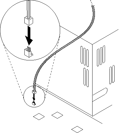
- Connect either end of the cable to the system board as shown in Figure 1.
Figure 1. Connecting the Wake on LAN cable to the system board (3-pin connector)
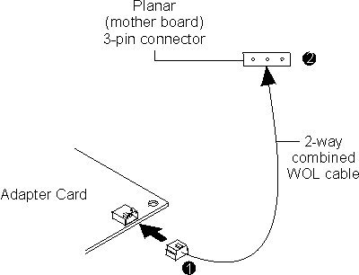
- Connect the other end of the cable to the adapter as shown at number
1 in Figure 2.
Figure 2. Connecting the 2-way combined Wake on LAN cable to the adapter
- Secure the adapter in the PCI slot with the retaining screw or other
bracket lockdown mechanism.
- Reinstall all removed covers.
- Connect the token-ring cable to the adapter and to the network. See
Selecting adapter cables for a description of the correct token-ring cables to
use.
- Reconnect all cables to your computer and then connect the power
cord. Follow all safety instructions.
| Note: | In the U.K., by law, the power cord must be connected before
the telephone line cable.
|
- The hardware installation is complete. See Software installation.
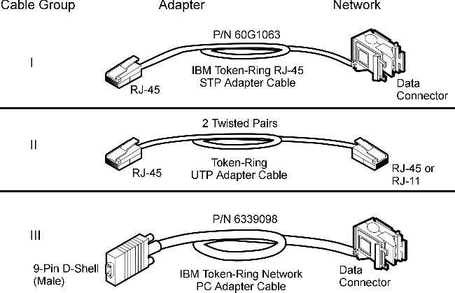
To connect your adapter to a token-ring network, you will need one of the
cables shown in Figure 3. These cables are not included with the
adapter.
Figure 3. STP and UTP cables
The network end of the cable must be compatible with the network faceplate
or other device to which the adapter will be connected.
| Note: | No more than one data cable may be connected to the adapter at a time.
|
Your adapter uses cables from group II (category 5 or better) or cables
from group III. You cannot use cables from group I. You cannot
use the combination of a conversion cable (PN 60G1066) with a cable from group
III.
[ Top of Page | Previous Page | Next Page | Table of Contents | Index ]


